VEE SPINE BEAM SYSTEM
Starting with the Vee Slab as the basic component, a fully self supporting long span precast building system called the Vee Spine Beam System has been developed and implemented on several projects.
The sequence of construction is as follows:
Precast columns are erected and propped for alignment and the starter bars grouted to into voids in the column base.


Next , prestressed Vee Spine Beams (Design Registered) are progressively erected and connected to the columns using a proprietary moment resisting connection system.

The Vee Spine Beams are connected near the inflection point of the continuous frame so consequently the finished frame behaves very closely to a continuous frame in both directions . This produces a very efficient frame which takes advantage of negative beam moments over the columns for all stages of loading and develops full sway bending moments for structural efficiency of the frame under vertical loading and from sway considerations.
Next, VeeSlabs are then laid between the Vee Spine Beams. At no stage is there need for the propping of Vee Spine beams nor Vee Slabs from the ground.

The Structure is then ready for top reinforcement and topping slabs which unify the structure and create continuity in the slabs and enhance the beam continuity. This is an ideal structural format for where it is very difficult to install falsework such as extending an existing building, building over water or other obstacle, building at high elevation above the ground or over severely undulating ground. This form of construction dispenses with backpropping which normally ties up at least 3 floors below the cast floor. This method results in very rapid and safe construction.
This system can be used for long spans and high loads. Additional Vee Spine Beams can be installed in the transverse direction to create transfer structures, examples of these are to be seen in the sample projects.
EXAMPLES OF VEE SPINE BEAM SYSTEM
GREGORY HILLS PROJECT MIXED USEAGE INCLUDING MEDICAL CENTRE OVER CAR PARK.

GENERAL VIEW OF MAIN DECK DURING ERECTION OF PRECAST FRAME

GENERAL UNDERSIDE VIEW OF MAIN DECK FROM CAR PARK LEVEL.
ONLY ALIGNMENT PROPPING OF COLUMNS USED DURING CONSTRUCTION. NOTE QUALITY OF FINISH AND FLATNESS OF VEE SLAB SOFFIT.
GREGORY HILLS DEVELOPMENT FULLY PRECAST SELF SUPPORTING FRAME.

5000 sq m of 13.5KPa live load floor over car park. Maximum span 11.6m. Whole floor self supporting during construction. Floor erected in 6 crane days.
NEW SYDNEY SEAPLANE BASE ROSE BAY

New Base

INSTALLING VEE SPINE BEAM

SEAPLANE BASE MAIN FLOOR UNDER CONSTRUCTION
CAWARRA RD CARINGBAH FACTORY WAREHOUSE AND OFFICES.
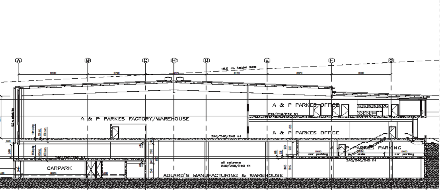
This building consists of 4 levels including 2500m of suspended 15KPa trafficable floor., offices , Factory slab on ground and suspended car park. It was built using the Vee System of precast columns , precast and prestressed Vee Spine Beams and Vee Slabs.
The two central Vee Slab Spans are 11m and the beam spans are typically 9m. The building was wholly erected by mobile cranes from the slab on ground.


Internal view from factory slab on ground to the underside of the 15KPa supended Vee System Floor. Note transfer structure for lifts and upper floor.8 m high columns and offset beams supporting car park to reduce column clutter in factory floor

Underside of 11m x 9m storage floor showing 8 m high columns

General View of underside of storage floor

Installing column/beam connection Note cranked beam layout.

Installing 11m Vee Slab span on Vee Spine beams
GLEDSWOOD HILLS MIXED STORAGE AND RETAIL DEVELOPMENT
This building comprises an external colonnade and first floor at a height of 6m. The external walls and columns were erected and propped and then the window sill spandrel panels forming the floor beam of the structure were then installed with moment connections to the columns and then the Vee System internal columns, beams and Vee Slabs installed and the floor topping poured to complete the floor and to provide the shear connections to the shear walls.

External vertical elements and window sill first floor spandrel beams installed level with the top of the external columns.

Vee Spine beams and Vee Slabs installed prior to pouring topping slab.
R.S.P.C.A. CATTERY BUILDING AND CAR PARK VEE SPINE STRUCTURE.


NOTE STRUCTURAL SPANDREL SUPPORTING SPINE BEAM


St George Sailing Club.


PRECAST ERECTION TOOK 3 DAYS FOR 1650 M2, INCLUDING BALUSTRADE PANELS.
3. VEE FLAT PLATE SYSTEM
By fitting landing tabs to the upper surface of Vee Slabs, one Vee Slab can be supported off another Vee Slab in the same plane. In this way Vee Slab Flat Plates can be built using various patterns of Vee Slabs to emulate two way flat plate structures.
Flat plates are common in the building industry as they offer thin floor depths and simplicity of installation of services .
Vee Flat Plates are more economic than the Vee Spine Systems as the Vee Slab components are much cheaper to produce than Spine Beams.
Vee Flat Plates are suitable for lighter loaded structures such as residential, offices and car parks.
The member which carries the load to the column is a specialized Vee Slab which is solid around the column and carries significant non stressed reinforcement in both directions. This members has its’ prestress profiled high over the column and low over the mid span. The Vee Slab Spine is joined at the point of inflection of the column strip to attain pseudo continuity during construction.
As with the other Vee Systems, the Vee Flat Plate is fully self supporting during construction so does not require any vertical propping with the subsequent gains in construction speed.
Although for optimal precasting efficiency a structure should have a high a level of repetition as possible, the Vee Plate Plate system can be adapted to irregular and misaligned column grids.
THE FOLOWING IS THE ERECTION SEQUENCE OF THE VEE FLAT PLATE SYSTEM.
After the columns are installed in a similar manner to the Vee Spine System:

VEE SPINE SLAB MEMBERS ARE ERECTED OVER INTERNAL COLUMNS

SECONDARY VEE SPINE MEMBERS ARE ERECTED TO THE EXTERNAL COLUMNS

EDGE VEE SLABS ARE INSTALLED

THE REMAINING INFILL VEE SLABS ARE INSTALLED READY FOR REINFORCEMENT AND TOPPING SLAB.
RSPCA YENNORA ADMINISTRATION BUILDING


UNDERSIDE VIEW OF VEE FLAT PLATE SYSTEM NOTE COLUMN VEE SPINE SLABS AND SECONDARY VEE SLAB PANELS.
MISCELLANEOUS APPLICATIONS
Doody St Bridge

SPECIALTY SKEWED VEE SLAB PANELS FOR ROAD BRIDGE AT DOODY ST ALEXANDRIA FOR HANNANPRINT. NOTE FILLED VOIDS TO ENHANCE SHEAR CAPACITY DURING CONSTRUCTION AND VOIDS REMOVED TO ENHANCE SHEAR FOR SERVICE LOADING, SHEAR CONNECTING REINFORCEMENT EXTENDING IN TO TOPPING SLAB TO ENHANCE SHEAR FATIGUE PERFORMANCE UNDER MOVING WHEEL LOADS.
THIS IS AN EXAMPLE OF THE ADAPTABILITY OF THE VEE SLAB SYSTEM.
VEE SLABS FOR THIS PROJECT WERE SPECIFIED BY THE PROJECT ENGINEERS , HENRY AND HYMAS.

DOODY ST ALEXANDRIA ROAD BRIDGE OVER CANAL

DOODY ST BRIDGE , UNDERSIDE VIEW OF PANELS FORMING BEAMS AND SLABS. 9.2M SPAN 275MM DEEP VEE SLABS.
DETENTION TANK ROOF LENORE LANE ERSKINE PARK.
CONSULTING ENGINEER: JOHN CAVASINNI AND ASSCOCIATES

THIS PROJECT INVOLVED THE CONSTRUCTION OF A ROOF OVER A ON SITE DETENTION TANK 39 METRES LONG AND 21 METRES WIDE.
THE ROOF NEEDED TO SUSTAIN ONE METRE OF SOIL FILL PLUS 15 KPa OF LIVE LOAD.
600MM SQUARE BLOCK PIERS WERE SPACED ON A 2.4M BY 7.0 M GRID WITH VEE SLABS BEING SUPPORTED ON THEIR CORNERS.
250mm DEEP VEE SLABS WITH 100mm OF TOPPING WERE USED.
VEE SLABS LAID WITH 100mm OF GAP BETWEEN THE ENDS OF PANELS AND MADE CONTINUOUS FOR LIVE LOAD IN BOTH DIRECTIONS.

VEE SLAB PANELS BEING INSTALLED

LENORE LANE ERSKINE PARK.
VEE SLAB INSTALLATION COMPLETE (10HOURS)
ROOF OVER OSD TANK AT OAKDALE FOR DHL.
BUILDER:TAYLOR CONSTRUCTIONS,
CONSULTING ENGINEER: COSTIN ROE .

THIS TANK IS 67 METRES LONG AND 8.0 METRES CLEAR SLAB.
THE ROOF IS DESIGNED FOR 2 B DOUBLE TRUCKS ANYWHERE AND 25KPa LIVE LOAD ACTING SEPARATELY.
250mm THICK VEE SLABS WERE USED WITH TAPERING TOPPING AVERAGEING 200 mm IN THICKNESS.


VEE SLAB WITH FRAMED PENETRATION BEING LIFTED

OAKDALE OSD ROOF VEE SLABS ERECTED IN BACKGROUND ( NOTE SHEAR CONNECTORS OUT OF VEE SLABS).


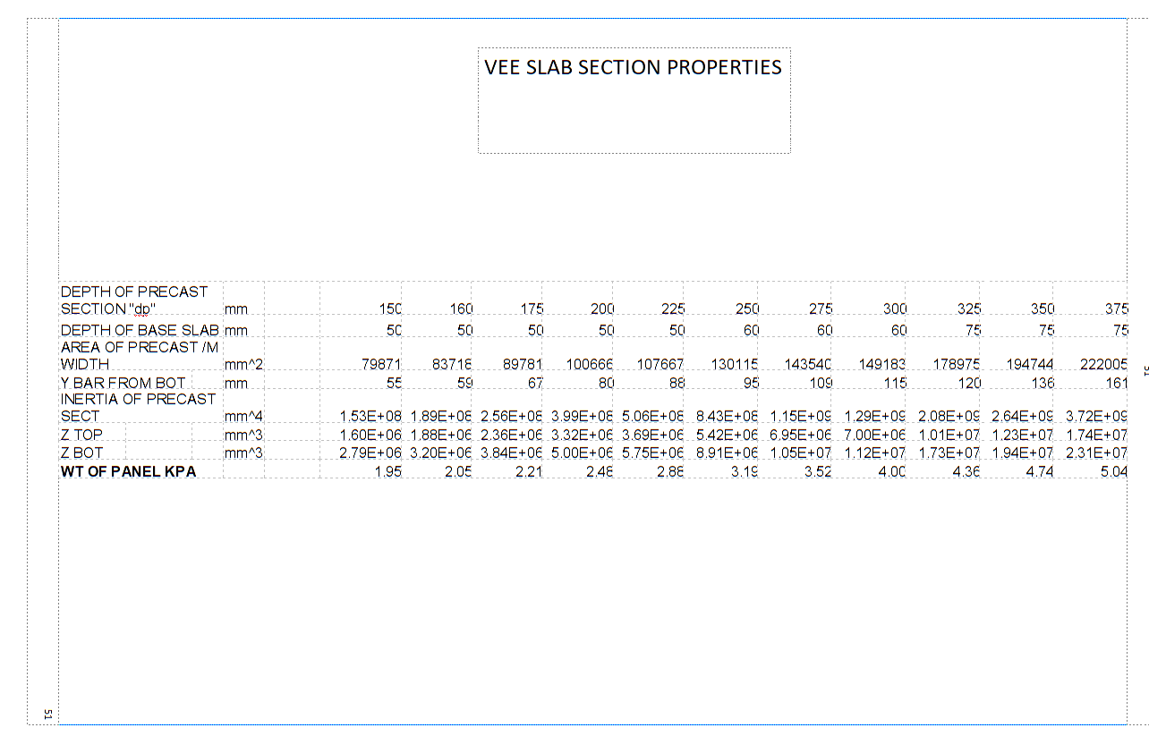
Ultimate Moment Capacity per meter completed floor in kN/m width of slab.
